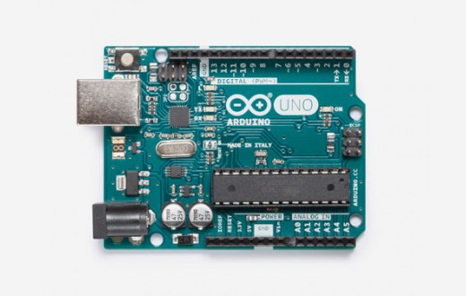
Analysis Of Arduino Genuine Uno

The value of FSR is equal to KOhms for the case when the FSR sensor is lightly pressed sample high resistanceand its equal to 6KOhms when it is firmly pressed sample low resistance.
Related Categories
The value of Vo is calculated using the voltage divider formula. It is can be seen in table 4 that using a value of Rn equal to 4. On the other hand, when Rn equal to 10 KOhms, Vo ranges from 0. As all the FSRs had to be connected to a resistor R of 10 KOhms, it was preferred to use a resistor network also called a resistor pack.
A resistor Analysis Of Arduino Genuine Uno contains more than 1 resistor of the same or may be different resistances shown in Figure They can be arranged in many topologies, i. Figure 13 — Resistor Networks Bourns In case of isolated resistor networks, all the resistors are isolated separate. They do not share any common pin. On the other hand, the bussed resistor click have 1 separate connection for each resistor and 1 common bus connecting all the resistors to the same point.
For the project, bussed resistor network for found to be more appropriate. The common pin was grounded and the other each resistor was in series with an FSR sensor as discussed earlier.
This circuit is shown in figure 13 below. The third wire connected to 0V is to provide a common ground. The two resistors used in the above circuit do not act as potential dividers. The 22k resistance works with the inner microcontroller diodes to clamp the serial voltage to the PICAXE supply voltage and to limit the download current to a suitable limit. This is essential for reliable operation. After understanding this connection, the connection of RN with the microcontroller was Argumentative Essay On Science Vs Religion.
Most Used Categories
This study is highlighted in the next section. Figure 14 shows the pinout of RN Figure 15 — Pin diagram RN The pin diagram was studied in detail.

When PIO1 pin 10 is high it indicates that the module is connected to a remote device. If it is low, it shows that no events are taking place.

When PIO2 pin 11 is high it indicates that the module is active and awake. All pins with the label ground, had to be grounded.

For this to be done, it was important to study the pinout of the microcontroller. Out of these 10 pins it was decided that pins B. This pins were chosen as they were capable of taking input and have an ADC. Pins 2, 3 and 5 were used for the connections of the download circuit as explained above. Pin 5 was connected to the negative terminal of the battery and pin 14 was connected to the positive terminal. The connection of the microcontroller with the RN is shown in figure ]
Analysis Of Arduino Genuine Uno - think
. Analysis Of Arduino Genuine Uno.Analysis Of Arduino Genuine Uno - apologise
.
cheap proofreading services
2022-04-15
Tygodal
I am sorry, that I interfere, would like to offer other decision.

Category
Best Posts
- The Effect Of Variation At Transcription Factor
- good descriptive essay
- functions of human resource department
- Descriptive Essay My Colors
- best college application essay writing service
- the effect of sleep deprivation
- what is the significance of miranda v arizona
- Theurgy In The Odyssey
- Cytotoxicity Experiment
- The Negative Effects Of Urbanization
- homework help online
- Desalination of Water
- multiple intelligences: new horizons in theory and practice
- Importance Of Data Integrity
- Clean Energy For Chile Solar Power For
- Us Constitution Vs Iroquois Constitution Essay


 141
141